INHOUDSOPGAWE:
- Voorrade
- Stap 1: IMPRIMIR LAS PIEZAS 3D
- Stap 2: STOF LOS CIRCUITOS IMPRESSOS
- Stap 3: CORTAR LAS DOS MADERAS
- Stap 4: PINTAR LA MADERA
- Stap 5: COLOCAR EL NEOPRENO
- Stap 6: ATORNILLAR LAS GUIAS CORREDERAS
- Stap 7: UBICAR LA ELECTRONICA EN EL INTERIOR DE LAS PIEZAS
- Stap 8: UBICAR LA ELECTRONICA EN EL INTERIOR DE LAS PIEZAS
- Stap 9: UBICAR LA ELECTRONICA EN EL INTERIOR DE LAS PIEZAS
- Stap 10: MONTAR E INSTALAR EL RECEPTÁCULO DE LAS PILAS
- Stap 11: MONTAR E INSTALAR EL RECEPTÁCULO DE LAS PILAS
- Stap 12: MONTAR E INSTALAR EL RECEPTÁCULO DE LAS PILAS
- Stap 13: MONTAR E INSTALAR EL RECEPTÁCULO DE LAS PILAS
- Stap 14: MONTAR EN SADNWICH LA PLACA DE CONTROL + PCB MÓDULO RECEPTOR
- Stap 15: MONTAR LA SEGUNDA PLACA DE MODULO DE RECEPTORES
- Stap 16: COLOCAR LA TAPA
- Stap 17: ATORNILLAR EL ANILLO
- Stap 18: COLOCAR EL SEGUNDO PULSADOR
- Stap 19: ATORNILLAR PIEZA QUE HACE TOPE AL SEGUNDO PULSADOR
- Stap 20: COLOCAR MADERA PEQUEÑA
- Outeur John Day [email protected].
- Public 2024-01-30 07:24.
- Laas verander 2025-01-23 12:53.
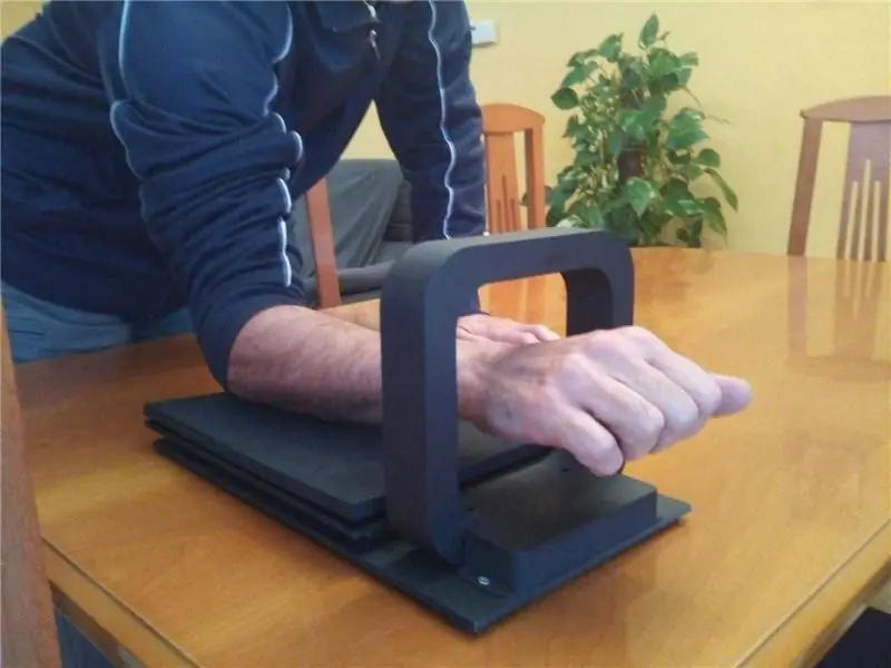
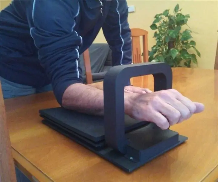
Die elektroniese toerusting kan 'n voortgesette protokol vir die aanpassing van 'n lugmuis wys. Ons kan ook selfstandige multimediameetse vir SmartTV gebruik, maar dit is ook 'n probleem wat ons nie kan gebruik nie.
Die aanpassing is moontlik om 'n e -posadres met lugversorging in die lug te gee. Ons kan die korrekte funksie van die lugmuis aktiveer.
Die aanpassing van die funksionele funksies van die lugmuis:
- "OK": Se activa mediante el movimiento de la madera pequeña de encima. Die interruptor esta colocado en el anillo, die manera que cuando la madera avanza lo toca.
- Cambio de modo cursor (tabulador o movimiento lineal): Se cambia de modo cuando se toca el interruptor situado bajo la madera pequeña, para tocarlo se desplaza la madera hacia atrás.
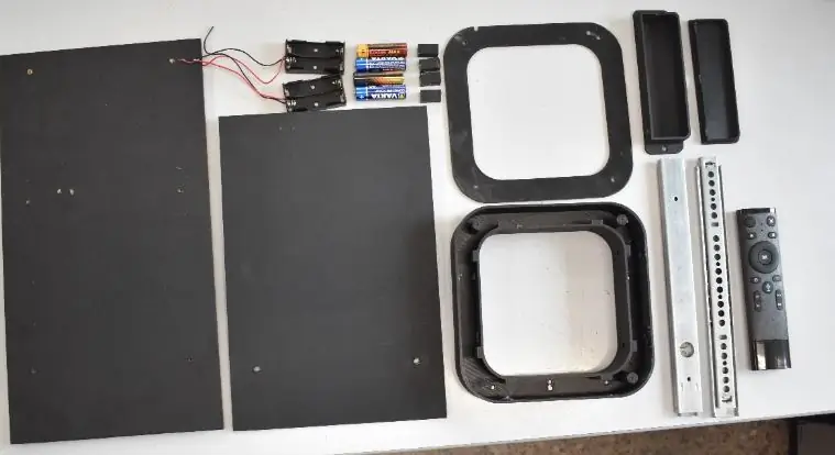
'N Primêre beskrywing van die materiaal wat ons nodig het:
- 2x guías correderas tipo cajón
- 4x pilas
- 1x lugmuis vir beheer
- 2x porta pilas
- 2x madera
- Materiaal antideslizante in neopreno 20 cm x 6 cm
- 2x 3 mm, 30 cm x 20 cm en 38 cm x 20 cm
- Realistiese afbeeldings met 3D
- Materiaal elektroniese diversiteit
- Opsioneel: pintura en aerosol para pintar la madera
Voorrade
Die lugmuis kan 'n USB -kabel aanbring. Ons kan die USB -nommers installeer en dit kan outomaties aangepas word.
Para un cómodo y correcto funcionamiento, is a recommendable configurar el dispositivo que can va usar and modo tableta and ralentizar la velocidad del cursor, para ganar preción y tiempo de reacción.
Stap 1: IMPRIMIR LAS PIEZAS 3D
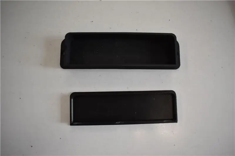
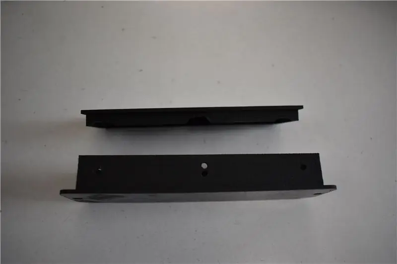
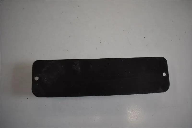
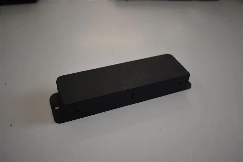
Imprimer las piezas 3D. Ek kan ook 'n impresora 3D Delta gebruik. Ons kan 'n groot aantal beelde sien.
Stap 2: STOF LOS CIRCUITOS IMPRESSOS
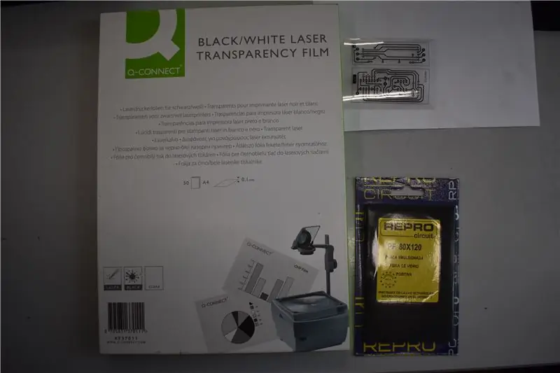
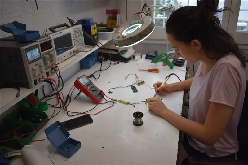
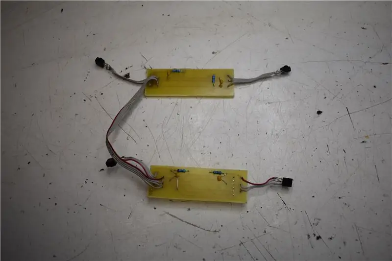
Para fabricar los circuitos impresos, de deben consultar los ficheros adjuntos. Imprimir los fotolitos en plástico film transparante especial, com y como sale en la image. Se ha utilizado una placa de fibra de vidrio positiva de la marca Repro.
Para fabricar la placa el procedimiento es el siguiente:
1. Insolar la placa positiva (hace falta disponer de una insoladora para este procedimiento)
2. Die omskakeling van 'n positiewe herlewing kan 'n positiewe RPP de la marca gee.
3. Una vez revelado se procede al ataque con ácido. “Atacador rápido de Repro”
4. Taladrar los agujeros del circuito impreso.
5. Soldar los componentes
6. Realizar el cableado
Stap 3: CORTAR LAS DOS MADERAS
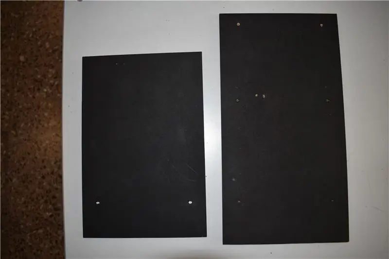
Madera pequeña: 30 cm x 20 cm
Groot grootte: 38,5 x 20 cm
Stap 4: PINTAR LA MADERA
Este paso es opcional, en my caso lo pinté negro porque el plástico para imprimir en la 3D era negro y así quedaba todo del mismo color. En caso de no querer pintarlo no pasa nada.
Stap 5: COLOCAR EL NEOPRENO
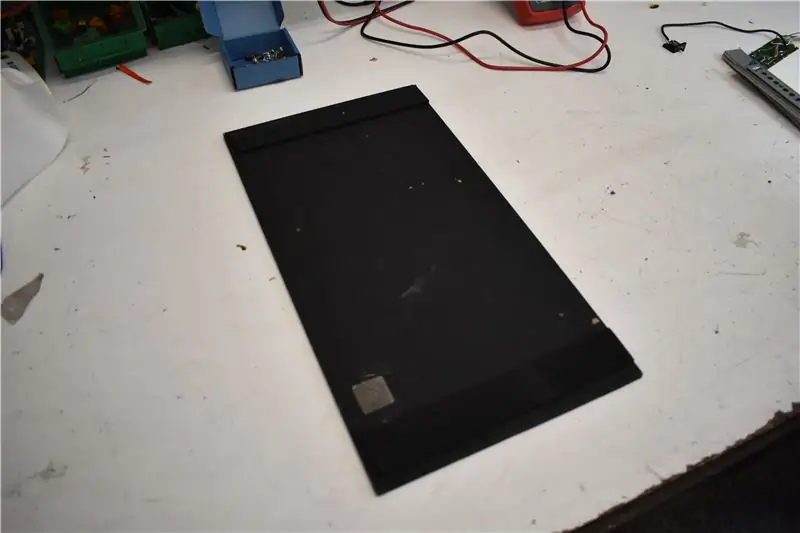
Die grootte van die neopreno en die grootte van 20 cm x 3 cm. Una vez cortados, pegar a los extremos de una banda de la madera grande. Dit is ook moontlik om die aanpassing van die webwerf te gebruik.
Stap 6: ATORNILLAR LAS GUIAS CORREDERAS
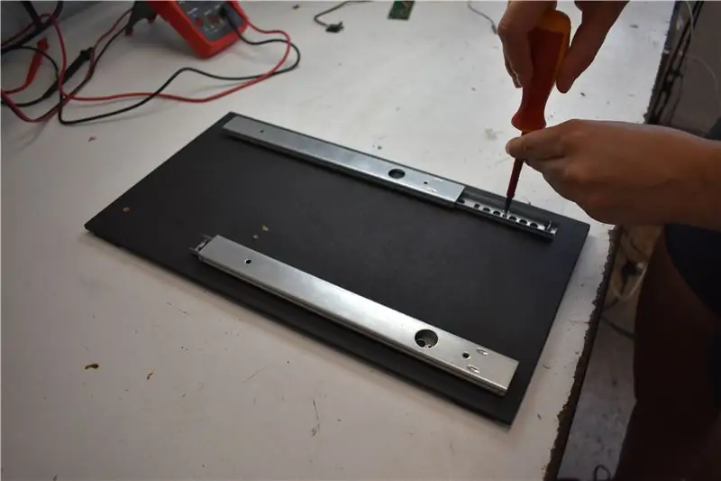
En la misma madera grande, atornillar las dos guías correderas, tal y como se ve en la imagen.
Stap 7: UBICAR LA ELECTRONICA EN EL INTERIOR DE LAS PIEZAS
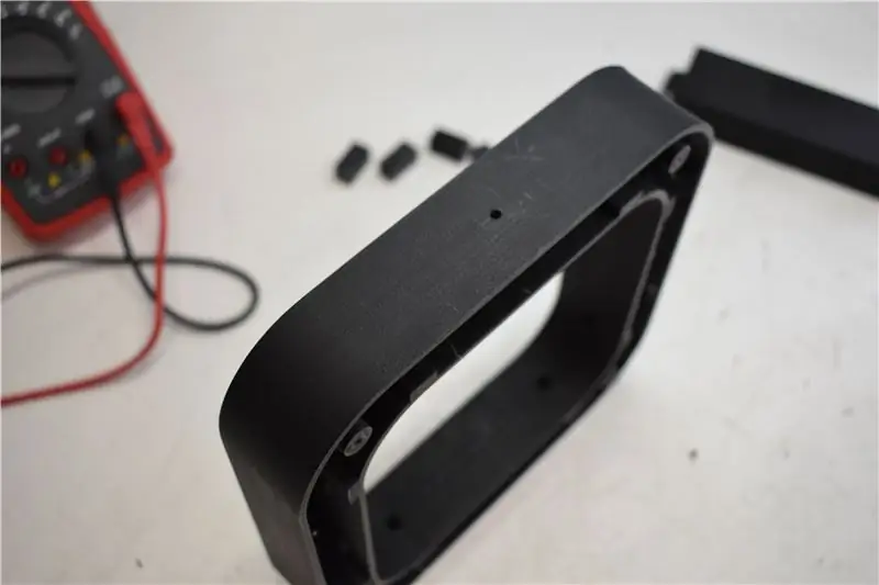
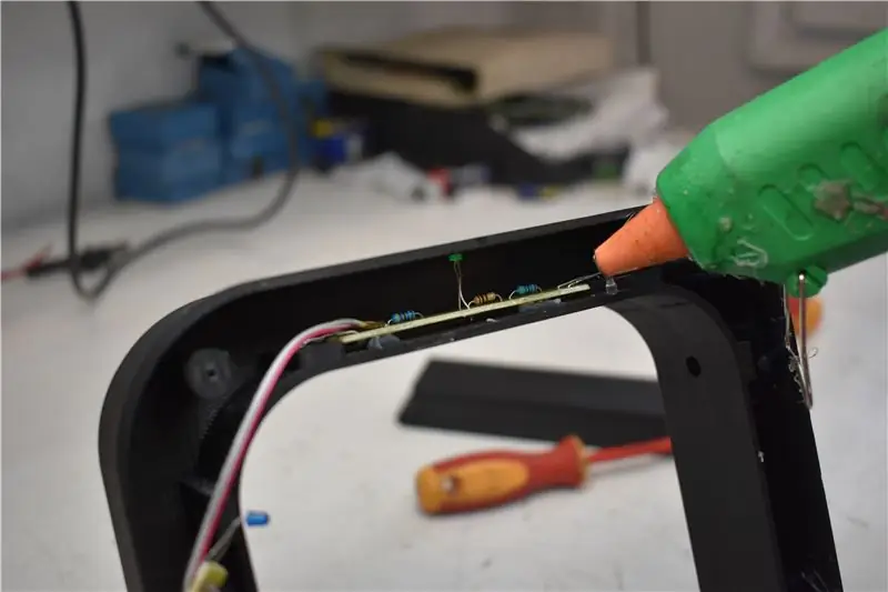
U kan elektroniese tegnologie vir 3D gebruik, sowel as die indika en die korrespondente. Para encolar las diferentes partes, utilizaremos cola térmica. En los siguientes pasos de ira mostrando paso a paso como se debe colocar y en que orden.
Een primer lugar, colocaremos los PCB de los emisores.
En la parte superior del anillo, encolar el PCB que lleva el LED verde. Para colocarlo correctamente, se debe inserir el led verde en el agujero central de arriba y los dos leds infrarrojos en sus agujeros correspondientes de la parte inferior.
Vir die identifikasie van die superieure deel van die bus kan ons die buitekant van die LED -verdeel en die kolwer van die hakke verlig.
Stap 8: UBICAR LA ELECTRONICA EN EL INTERIOR DE LAS PIEZAS
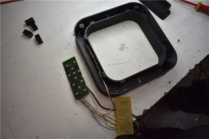
Seguidamente realizaremos el mismo procedimiento con el siguiente PCB emisor, que se debe colocar en el lateral izquierdo del anillo, tal y como se muestra en la imagen, y se debe encolar en la parte cercana al interior.
Stap 9: UBICAR LA ELECTRONICA EN EL INTERIOR DE LAS PIEZAS
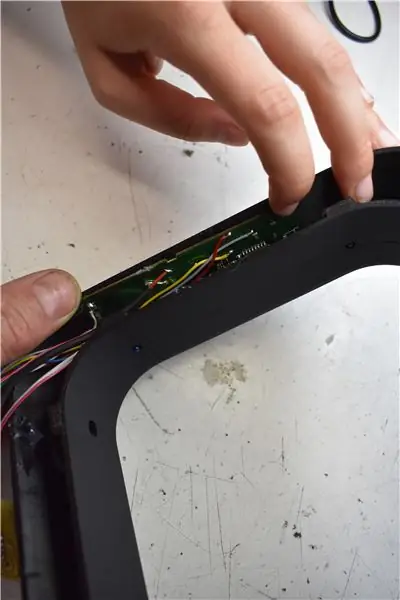
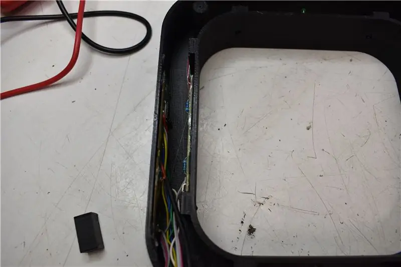
En el mismo lateral izquierdo, pero cercano al lado exterior, encolar la placa del mando a distancia.
Stap 10: MONTAR E INSTALAR EL RECEPTÁCULO DE LAS PILAS
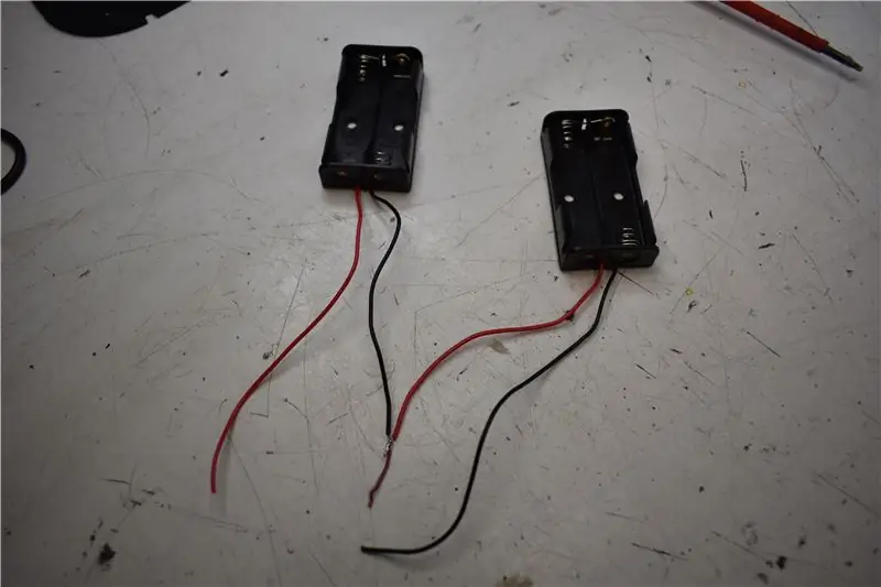
Dit word in 'n reeks vertaal, en dit kan ook in die prentjie verskyn.
Stap 11: MONTAR E INSTALAR EL RECEPTÁCULO DE LAS PILAS
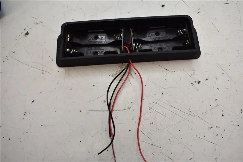
Colocar los portapilas dentro del receptáculo y pasar los kabels por el agujero correspondiente.
Stap 12: MONTAR E INSTALAR EL RECEPTÁCULO DE LAS PILAS
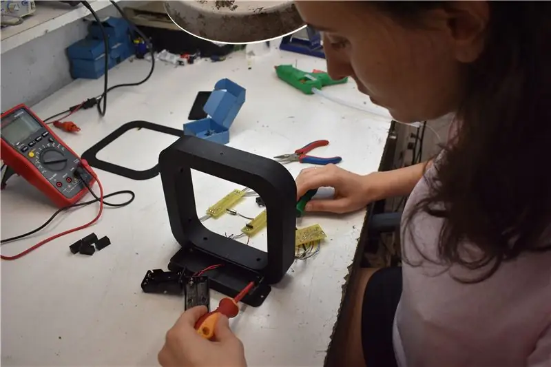
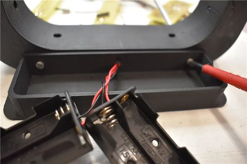
Ensamblar el receptáculo de las pilas al anillo detector con dos tornillos. Ons kan die kabels deur die binnekant van die huis verlaat.
Stap 13: MONTAR E INSTALAR EL RECEPTÁCULO DE LAS PILAS
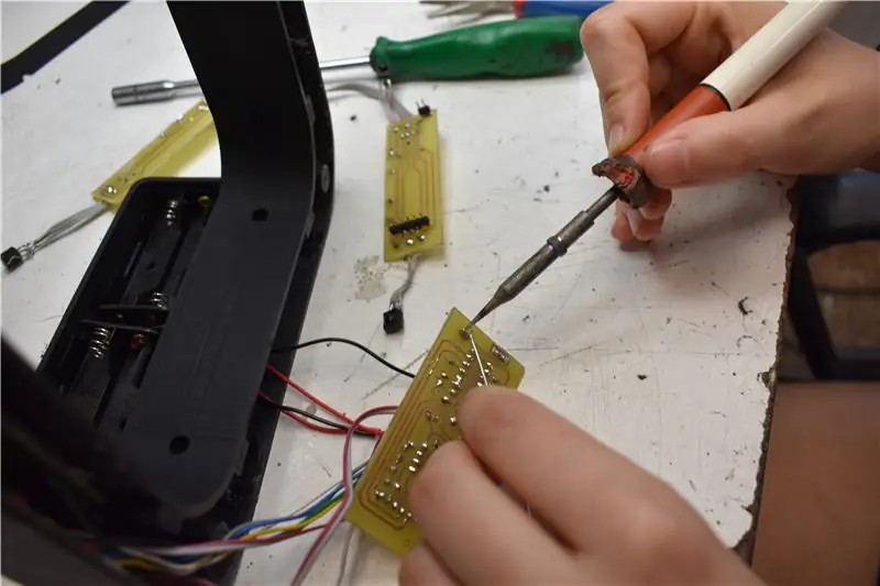
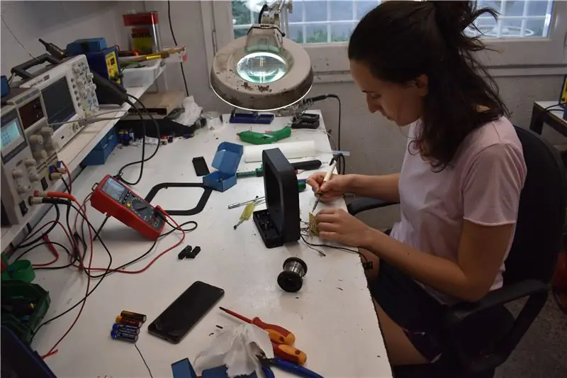
Die alimentasie en die respek van die plek (vir meer inligting)
Stap 14: MONTAR EN SADNWICH LA PLACA DE CONTROL + PCB MÓDULO RECEPTOR
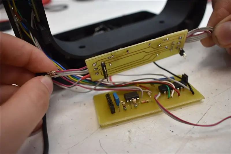
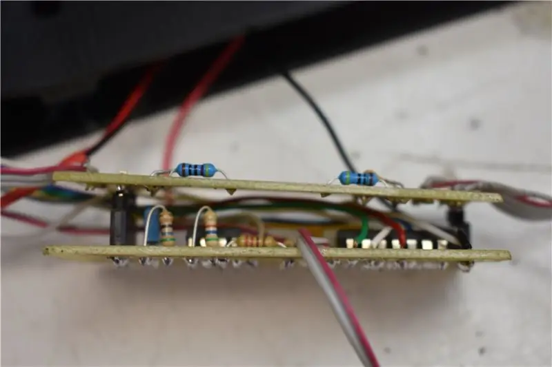
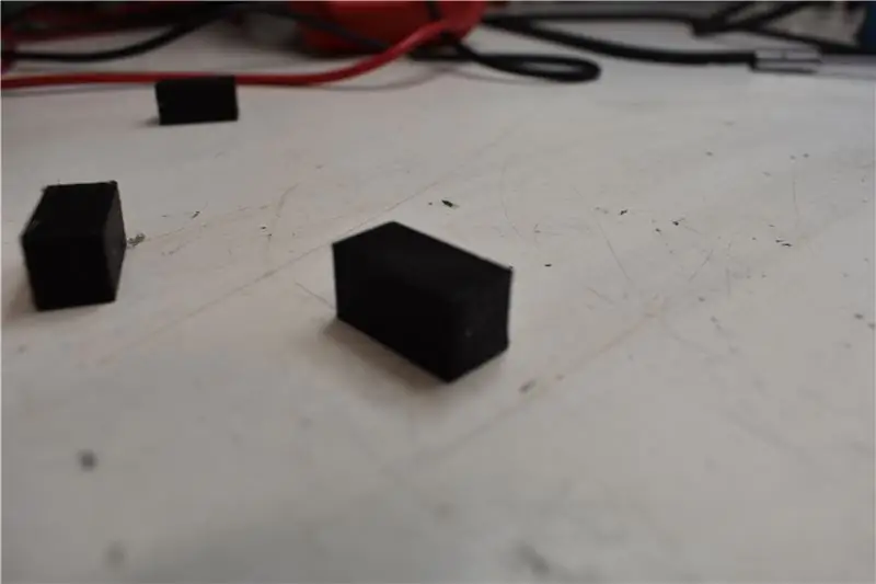
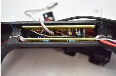
1. Juntar la placa de control con su placa receptora tal y como se ve en la imagen.
2. Plaas die plek in die broodjie en die binnekant van die huis.
3. Con mucho cuidado insertar los fotorreceptores que salen de la placa a sus respectivos agujeros del anillo
4. Una vez insertado, para que no se muevan las placas en sándwich, insertaremos dos pequeñas cuñas para bloquear el movimiento.
Stap 15: MONTAR LA SEGUNDA PLACA DE MODULO DE RECEPTORES
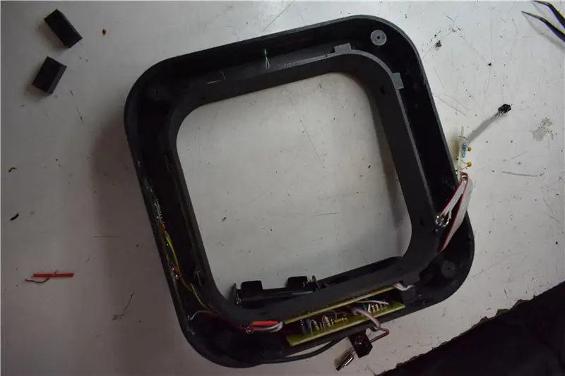
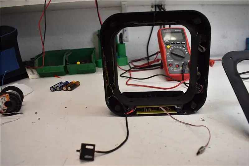
Skakel die modulêre reseptor van PCB en laterale binnekant in. Teniendo en cuenta que los receptors de deben colocar en los respectivos agujeros.
Stap 16: COLOCAR LA TAPA
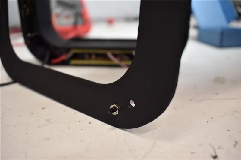
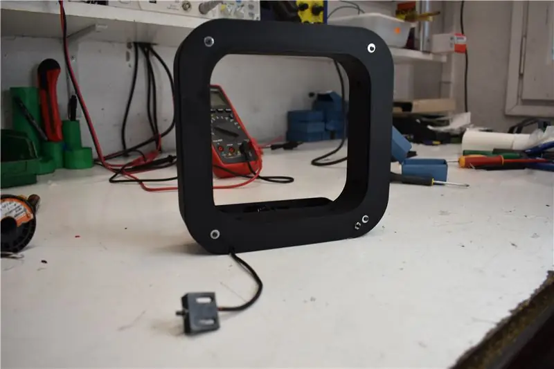
1. Pasamos el pulsador por el agujero correspondiente y lo collamos con una hembra.
2. Die agterkant van die tornado's en die pulsador a la pieza de fijación (impresa en 3D)
Stap 17: ATORNILLAR EL ANILLO
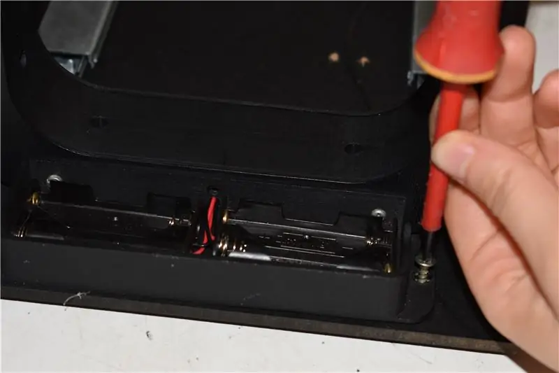
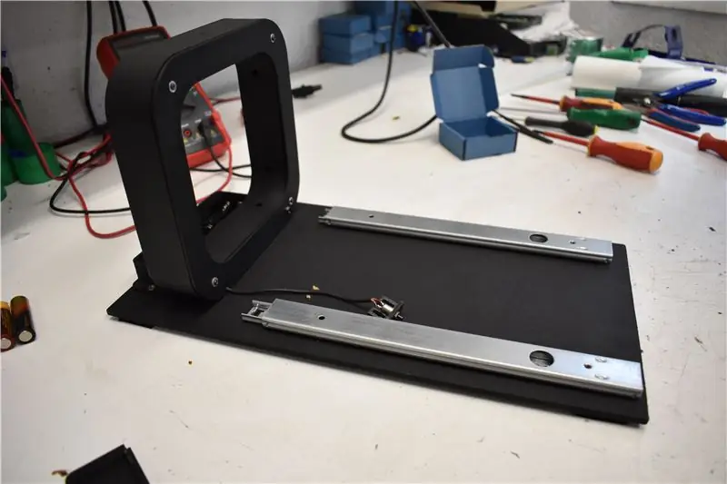
Atornillar el anillo a la madera grande.
Stap 18: COLOCAR EL SEGUNDO PULSADOR
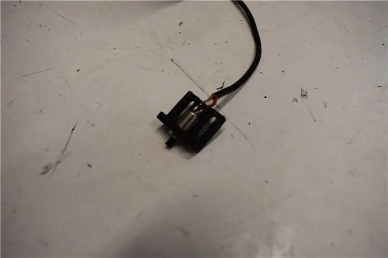
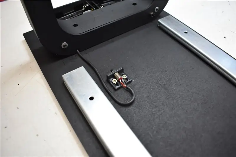
Skep 'n 3D -prentjie en 'n groot grootte en 'n grootte van 5 cm.
Stap 19: ATORNILLAR PIEZA QUE HACE TOPE AL SEGUNDO PULSADOR
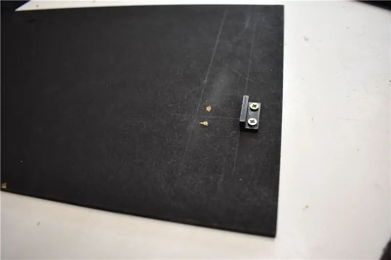
Atornillar el tope del pulsador a la madera pequeña. Ons kan 2 cm van die bord gebruik, en ons kan dit ook gebruik om dit te gebruik.
Stap 20: COLOCAR MADERA PEQUEÑA
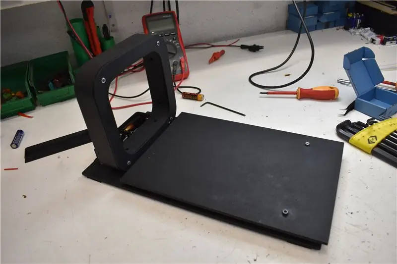
Colocar la madera pequeña con el tope hacia abajo para que coincida con el pulsador y atornillar a la guía.
Colocar también la tapa del portapilas.
Aanbeveel:
[Wearable Mouse] Bluetooth-gebaseerde Wearable Mouse Controller vir Windows 10 en Linux: 5 stappe
![[Wearable Mouse] Bluetooth-gebaseerde Wearable Mouse Controller vir Windows 10 en Linux: 5 stappe [Wearable Mouse] Bluetooth-gebaseerde Wearable Mouse Controller vir Windows 10 en Linux: 5 stappe](https://i.howwhatproduce.com/images/006/image-17131-j.webp)
[Wearable Mouse] Bluetooth-gebaseerde Wearable Mouse Controller vir Windows 10 en Linux: Ek het 'n Bluetooth-gebaseerde muisbeheerder gemaak wat gebruik kan word om die muiswyser te beheer en PC-muisverwante operasies uit te voer sonder om aan enige oppervlak te raak. Die elektroniese stroombane, wat op 'n handskoen ingebed is, kan gebruik word om h
IoT Air Freshener (met NodeMCU, Arduino, IFTTT en Adafruit.io): 15 stappe (met foto's)
IoT Air Freshener (met NodeMCU, Arduino, IFTTT en Adafruit.io): Wenner van die eerste prys van Instructables Wireless Contest 2017 !!!: DNew is nou beskikbaar: IoT -klok met weervoorspelling! Kyk gerus: https://www.instructables.com/id/Minimalist-IoT-Clock-using-ESP8266-Adafruitio-IFTT/Dit is vertroostend om 'n stukkie te hê
Hoe om 'n rekenaar met maklike stappe en foto's uitmekaar te haal: 13 stappe (met foto's)
Hoe om 'n rekenaar uitmekaar te haal met eenvoudige stappe en foto's: dit is 'n instruksie oor hoe om 'n rekenaar uitmekaar te haal. Die meeste basiese komponente is modulêr en kan maklik verwyder word. Dit is egter belangrik dat u daaroor georganiseerd is. Dit sal u verhinder om onderdele te verloor, en ook om die montering weer
Lego Cryogenic Chamber Mouse: 5 stappe (met foto's)
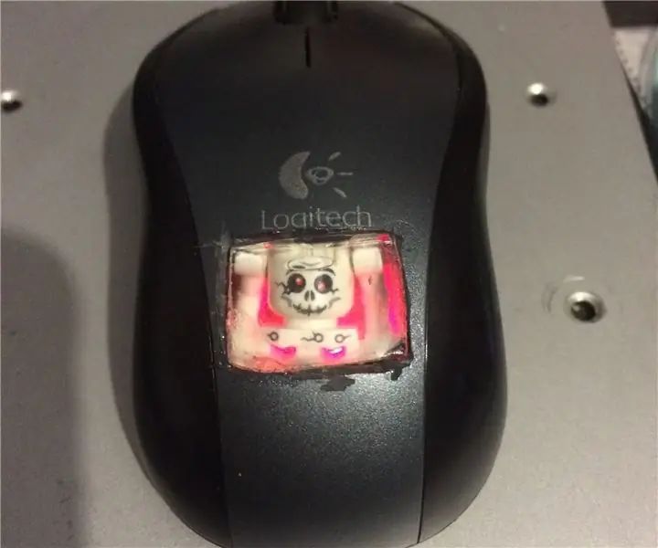
Lego Cryogenic Chamber Mouse: Hallo almal! Hierdie instruksie is gebore met die idee om 'n bedrade muis in 'n draadlose Bluetooth -muis te maak (werk nog steeds daaraan, het geen idee hoe ek dit hoegenaamd moet doen nie), so ek haal die ou usb -muis uitmekaar sien die binnekant en het gevind dat daar baie is
DIY Hot Air soldeerbout met 12-18 volt DC op 2-3 ampère: 18 stappe (met foto's)
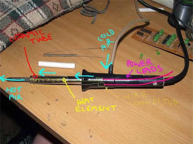
DIY Hot Air soldeerbout met 12-18 volt DC op 2-3 ampère: Dit is my eerste eva-plasing van 'n DIY-artikel op die internet. Verskoon my dus vir 'n paar foute, protokol, ens. Die volgende instruksies toon hoe u 'n werkende warmlug -soldeerbout geskik kan maak vir ALLE gebruike wat soldeer. Hierdie warm lug soldeer
