
INHOUDSOPGAWE:
- Outeur John Day [email protected].
- Public 2024-01-30 07:25.
- Laas verander 2025-01-23 12:53.


En este proyecto se mostrara, el funcionamiento y el como hacer para elaborar un un "Two wheel balance robot" paso a paso y con explicación y concejos. Dit is 'n stelsel wat bestaan uit 'n robot wat nie 'n debeer kan wees nie, en ook 'n gegewe punt van 0 of meer as 'n oorspronklike weergawe.
Stap 1: Stap 1: Materiaalvereiste
o Mecánicos:
a. 1 metro de varilla roscada (3/8)
b. 14 tornillos M3 x.07 x 6
c. 24 tuercas M8 heks
d. 3 tornillos M4 x.07 x 6
e. Filamento PLA (ongeveer 500 gram)
o Elektrisiteit:
a. 1 onderbrekerskakelaar
b. Arduino uno o nano
c. 2 motors behalwe 17
d. 2 bestuurders A4988
e. 3 weerstand 1k
f. HC-05
g. MPU-6050
h. 2 kapasitors van 100uf of 47uf
ek. Batería lippo 11.1 V
o Piezas fabricadas:
a. 3 plase van MDF (120 x 170 x 6 mm)
b. Placa PCB (ongeveer 8 x 14 cm)
c. Soporte batería
d. 2 motors vir motor
e. 2 lantas
o Ekstras:
Sagteware aanbeveel vir die realisering van projekte.
a. Arduino IDE sagteware
b. SolidWorks 2018
c. Kidcad sagteware
Stap 2: Stap 2: Sistema Mecánico-estructura
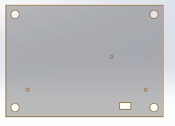
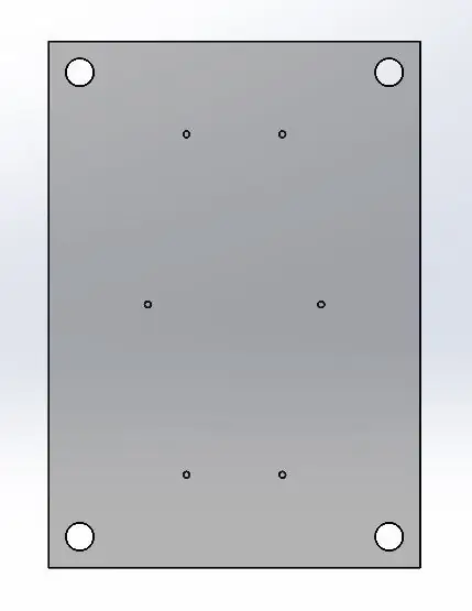
Die model van die pizzas en die algemene strukture van RealWork in SolidWorks, die eerste vorm van die MDF vir die verskaffing van spesiale funksies vir die agterkant. Estas placas son diferentes entre ellas, la placa inferior tendrá los orificios para los soportes de motores y batería, la central for nuestra PCB y la superior solo tendrá los orificios para darle su estructura.
Stap 3: Stap 3: Fabricación De Piezas 3D
Para el modelado de los soportes y llantas igualmente utilizosos SolidWorks, estos soportes pueden ser modificados si así lo desean, para un major funcionamiento, los soportes tienen orificios de.35 cm de dimetro, for una major sujeción.
Stap 4: Stap 4: Sistema Eléctrico/electrónico
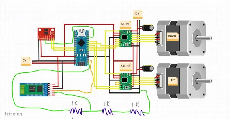
Ons kan ook 'n PCB gebruik, sowel as 'n aantal ooreenstemmende e-posse, sowel as Bluetooth HC-05, en 'n giroscopio van 6050 motors. Las conexiones son las que se muestran en la image. Asegúrese de hacer las conexiones correctamente, ya que de no ser así puede ocasionar que el sistema no funcione correctamente y no lo obedezca.
Stap 5: Stap 5: Sagteware
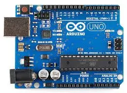
Para ela programa utilizamos un arduino, a continuación anexamos una parte de la programación with su explicación correspondiente, al igual anexo link, with el codigo complete:
Pos hou konfigurasie
// verstek POSHOLD beheer winste
#definieer POSHOLD_P 2.00
#definieer POSHOLD_I 0.0
#definieer POSHOLD_IMAX 20 // grade
#definieer POSHOLD_RATE_P 2.0
#defineer POSHOLD_RATE_I 0.08 // Windbeheer
#definieer POSHOLD_RATE_D 0.045 // probeer 2 of 3 vir POSHOLD_RATE 1
#definieer POSHOLD_RATE_IMAX 20 // grade
// standaard Navigasie PID winste
#definieer NAV_P 1.4
#definieer NAV_I 0.20 // Windbeheer
#definieer NAV_D 0.08 //
#definieer NAV_IMAX 20 // grade
#define MINCHECK 1100
#definieer MAXCHECK 1900
Dit kan veranderings in winste in verband met die stelsel behou.
Konfigurasie gyro:
ongeldig Gyro_init () {
TWBR = ((F_CPU / 400000L) - 16) / 2; // verander die I2C -kloksnelheid na 400kHz
i2c_writeReg (MPU6050_ADDRESS, 0x6B, 0x80); // PWR_MGMT_1 - DEVICE_RESET 1
vertraging (5);
i2c_writeReg (MPU6050_ADDRESS, 0x6B, 0x03); // PWR_MGMT_1 - SLAAP 0; SIKLUS 0; TEMP_DIS 0; CLKSEL 3 (PLL met Z Gyro -verwysing)
i2c_writeReg (MPU6050_ADDRESS, 0x1A, MPU6050_DLPF_CFG); // CONFIG - EXT_SYNC_SET 0 (deaktiveer invoerpen vir datasinkronisering); standaard DLPF_CFG = 0 => ACC -bandwydte = 260Hz GYRO -bandwydte = 256Hz)
i2c_writeReg (MPU6050_ADDRESS, 0x1B, 0x18); // GYRO_CONFIG - FS_SEL = 3: Volskaal ingestel op 2000 grade/sek
// aktiveer I2C -omseil vir AUX I2C
#as gedefinieer (MAG)
i2c_writeReg (MPU6050_ADDRESS, 0x37, 0x02); // INT_PIN_CFG - INT_LEVEL = 0; INT_OPEN = 0; LATCH_INT_EN = 0; INT_RD_CLEAR = 0; FSYNC_INT_LEVEL = 0; FSYNC_INT_EN = 0; I2C_BYPASS_EN = 1; CLKOUT_EN = 0
#endif
}
ongeldig Gyro_getADC () {
i2c_getSixRawADC (MPU6050_ADDRESS, 0x43);
GYRO_ORIENTATION (((rawADC [0] 2, // reeks: +/- 8192; +/- 2000 deg/sek.
((rawADC [2] 2, ((rawADC [4] 2);
GYRO_Common ();
}
ongeldig ACC_init () {
i2c_writeReg (MPU6050_ADDRESS, 0x1C, 0x10); // ACCEL_CONFIG-AFS_SEL = 2 (Volskaal = +/- 8G); ACCELL_HPF = 0 // let op iets is verkeerd in die spesifikasie.
// let wel: dit lyk asof hier iets verkeerd is in die spesifikasie. Met AFS = 2 1G = 4096 maar volgens my meting: 1G = 2048 (en 2048/8 = 256)
// hier bevestig:
#as gedefinieer (MPU6050_I2C_AUX_MASTER)
// in hierdie stadium word die MAG gekonfigureer via die oorspronklike MAG init -funksie in die I2C -omseilmodus
// nou stel ons MPU op as 'n I2C Master -toestel om die MAG te hanteer via die I2C AUX -poort (hier gedoen vir HMC5883)
i2c_writeReg (MPU6050_ADDRESS, 0x6A, 0b00100000); // USER_CTRL - DMP_EN = 0; FIFO_EN = 0; I2C_MST_EN = 1 (I2C -hoofmodus); I2C_IF_DIS = 0; FIFO_RESET = 0; I2C_MST_RESET = 0; SIG_COND_RESET = 0
i2c_writeReg (MPU6050_ADDRESS, 0x37, 0x00); // INT_PIN_CFG - INT_LEVEL = 0; INT_OPEN = 0; LATCH_INT_EN = 0; INT_RD_CLEAR = 0; FSYNC_INT_LEVEL = 0; FSYNC_INT_EN = 0; I2C_BYPASS_EN = 0; CLKOUT_EN = 0
i2c_writeReg (MPU6050_ADDRESS, 0x24, 0x0D); // I2C_MST_CTRL - MULT_MST_EN = 0; WAIT_FOR_ES = 0; SLV_3_FIFO_EN = 0; I2C_MST_P_NSR = 0; I2C_MST_CLK = 13 (I2C slawe spoed bus = 400kHz)
i2c_writeReg (MPU6050_ADDRESS, 0x25, 0x80 | MAG_ADDRESS); // I2C_SLV0_ADDR - I2C_SLV4_RW = 1 (leesbewerking); I2C_SLV4_ADDR = MAG_ADDRESS
i2c_writeReg (MPU6050_ADDRESS, 0x26, MAG_DATA_REGISTER); // I2C_SLV0_REG - 6 databytes van MAG word in 6 registers gestoor. Eerste registeradres is MAG_DATA_REGISTER
i2c_writeReg (MPU6050_ADDRESS, 0x27, 0x86); // I2C_SLV0_CTRL - I2C_SLV0_EN = 1; I2C_SLV0_BYTE_SW = 0; I2C_SLV0_REG_DIS = 0; I2C_SLV0_GRP = 0; I2C_SLV0_LEN = 3 (3x2 grepe)
#endif
}
ongeldig ACC_getADC () {
i2c_getSixRawADC (MPU6050_ADDRESS, 0x3B);
ACC_ORIENTATION (((rawADC [0] 3, ((rawADC [2] 3, ((rawADC [4] 3);
ACC_Common ();
}
// Die MAG -verkrygingsfunksie moet vervang word, want ons praat nou met die MPU -toestel
#as gedefinieer (MPU6050_I2C_AUX_MASTER)
ongeldig Device_Mag_getADC () {
i2c_getSixRawADC (MPU6050_ADDRESS, 0x49); // 0x49 is die eerste geheue kamer vir EXT_SENS_DATA
#as gedefinieer (HMC5843)
MAG_ORIENTATION (((rawADC [0] << 8) | rawADC [1]), ((rawADC [2] << 8) | rawADC [3]), ((rawADC [4] << 8) | rawADC [5]));
#endif
#as gedefinieer (HMC5883)
MAG_ORIENTATION (((rawADC [0] << 8) | rawADC [1]), ((rawADC [4] << 8) | rawADC [5]), ((rawADC [2] << 8) | rawADC [3]));
#endif
#as gedefinieer (MAG3110)
MAG_ORIENTATION (((rawADC [0] << 8) | rawADC [1]), ((rawADC [2] << 8) | rawADC [3]), ((rawADC [4] << 8) | rawADC [5]));
#endif
}
#endif
#endif
Stap 6: Stap 6: Consejos
1. Diseño Mecánico: Gebruik en gebruik dit in verskillende opsigte, vir meer as een keer kan ons 'n robot, 'n ander todo bien, vir 'n hora de hacer cortes láser of impresiones in 3D doen, sonder om dit te volg verlang a la perfección.
2. Diseño eléctrico: Hacer su propia PCB, para que tengan bien ubicadas las conexiones que tienen que hacer, de igual manera hacer primero las conexiones en una protoboard, para comprobar que cuando la pongan en el PCB el funcionamiento sea el correcto y no teng Dit is moontlik om meer as een prentjie van die PCB te gebruik.
3. Verskeie sagteware: 'n funksionele basis vir die program, maar ook 'n funksionele funksie vir 'n funksionele funksie en 'n funksionele funksie vir die funksie van 'n funksionele program.
Aanbeveel:
Tower Climb Helping Robot V1 - Twee -been, RF, BT -beheer met app: 22 stappe (met foto's)
Tower Climb Helping Robot V1 - Two Legged, RF, BT Control With App: As ek ooit akkedisse op mure sien, is ek van plan om 'n robot soos dit te maak. Dit is 'n langtermyn-idee; ek soek baie artikels na elektro-kleefmiddels en kyk of dit nie in staat was om dit te hou nie. Ek is nou eers van plan om dit met behulp van elektromagnet te maak om
Self -balanserende robot met twee wiele: 4 stappe
Self-balanserende robot met twee wiele: na my beskeie mening is u nie 'n regte maker nie, tensy u nie u eie selfbalanseerrobot met twee wiele bou nie. :-) So, hier is dit … !!! Hierdie projek lyk baie eenvoudig. Dit verg eerder 'n goeie kennisvlak van
Hoe om 'n DIY Bartop -arcade vir twee spelers te maak met aangepaste markies, met 'n Pandora -boks: 17 stappe (met foto's)

Hoe om 'n DIY Bartop -arcade vir twee spelers te maak met aangepaste markiesmuntstukke, met behulp van 'n Pandora -boks: dit is 'n stap -vir -stap handleiding oor hoe om 'n boonste arcade -masjien vir twee spelers te bou met persoonlike muntstukke wat in die markie ingebou is. Die muntstukke sal so gemaak word dat dit slegs munte aanvaar wat die grootte van 'n kwartier of groter is. Hierdie arcade word aangedryf
Eenvoudige Micro: bit -robot met Lego Technics -wiele: 5 stappe
Eenvoudige Micro: bit robot met Lego Technics wiele: hierdie instruksie gaan oor die gebruik van 'n baie eenvoudige onderstel met 2 stukke 5 mm perspex wat ek gesny en geboor het, sodat ek 'n Micro: bit robot so vinnig as moontlik aan die gang kon kry. Ek het geen elektriese gereedskap gebruik nie, behalwe vir 'n
Motor met parallelle stroombaan (3 wiele): 8 stappe
Motor met parallelle stroombaan (3 wiele): Hierdie motor kan teen 'n ordentlike pas oor plat oppervlaktes ry, en is 'n goeie les oor hoe om 'n parallelle stroombaan op te stel
